Mullite Applications and Process Optimization
Mullite-based insulating firebrick (mullite-based IFB) in energy-saving retrofits for protective-atmosphere heat-treatment furnaces is both a material method to "reduce wall heat transfer" and a system method to "reduce thermal mass." Using protective-atmosphere heat treatment for coils/long products (batch or continuous) as the typical scenario, this article provides a practical integrated lining material and structure plan, and explains how Xinhui uses computational methods to turn formulation optimization and batch consistency into an engineering workflow.
1. Process scenario: what determines energy use in protective-atmosphere heat-treatment furnaces
Typical temperature ranges cover 800-1000 deg C, and the production cadence is "heat-up -> soak -> controlled cooling/cooling." For this furnace type, specific energy use usually combines three losses:
- Shell heat loss (surface loss): higher shell surface temperature means higher heat flux;
- Sensible heat of exhaust/atmosphere gases: related to combustion systems and heat recovery;
- Lining thermal mass: during cyclic heating, energy is first consumed to heat the walls, especially evident when cadence is short and starts/stops are frequent.
Public industry cases provide an order-of-magnitude comparison: a coil annealing process under "typical conditions" is about 178 kWh/t, which can drop to about 124 kWh/t with heat recovery, saving 54 kWh/t (30.3%). This shows the realistic energy scale and the potential for system-level savings.
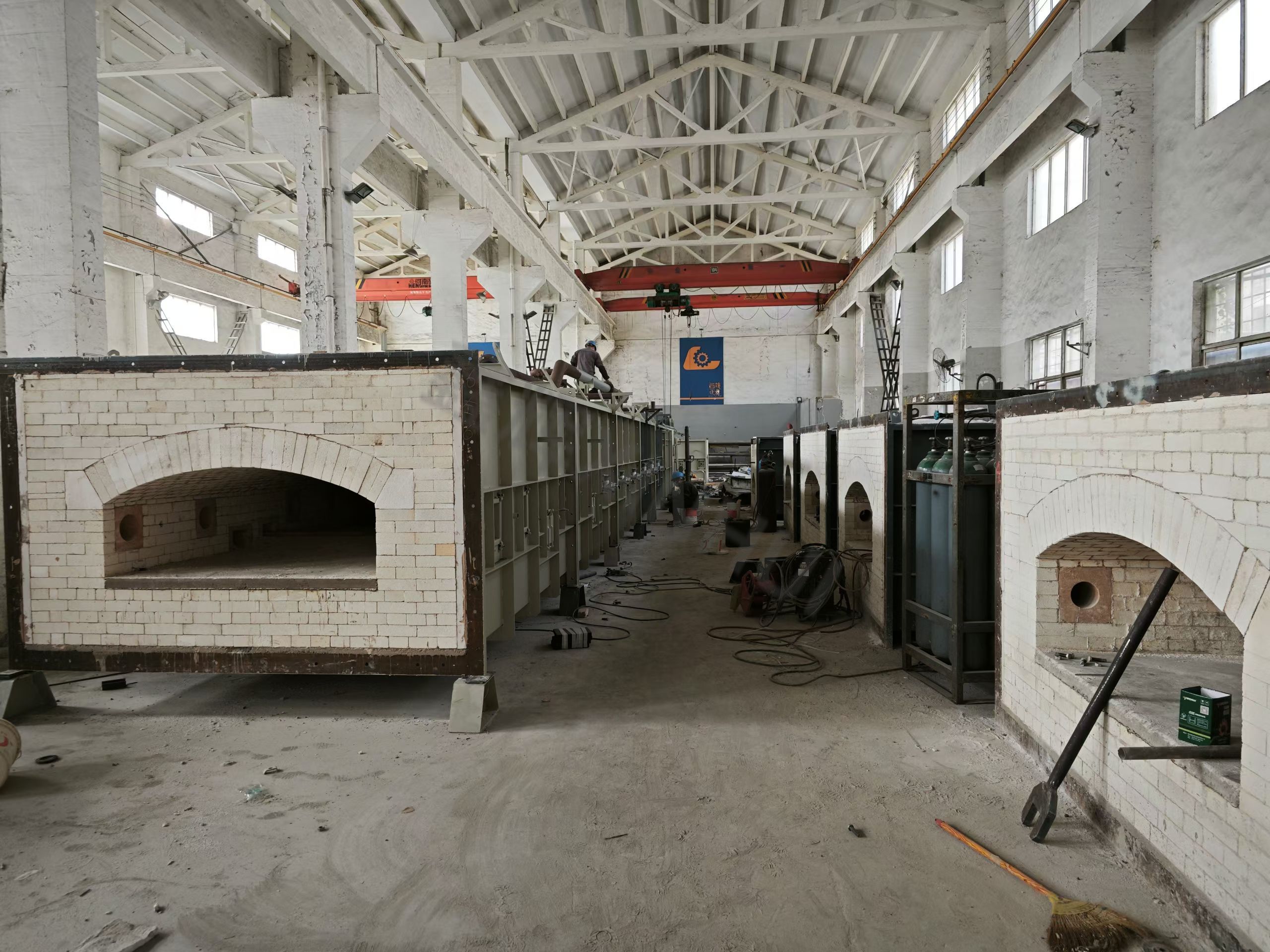
A metal products kiln line
2. Why shell heat loss must be reduced first
Energy balance studies repeatedly identify shell surface heat loss as a major item. One public measurement example:
- Surface loss is about 34% of input heat.
- Measured surface heat flux is about 631 W/m^2.
- Corresponding shell surface temperature is about 77 deg C.
- A more ideal target is about 200 W/m^2 and 40 deg C.
The engineering meaning is direct: as long as the lining structure and construction quality keep the shell surface temperature high, any combustion optimization or heat recovery will have part of its gains offset by wall leakage.
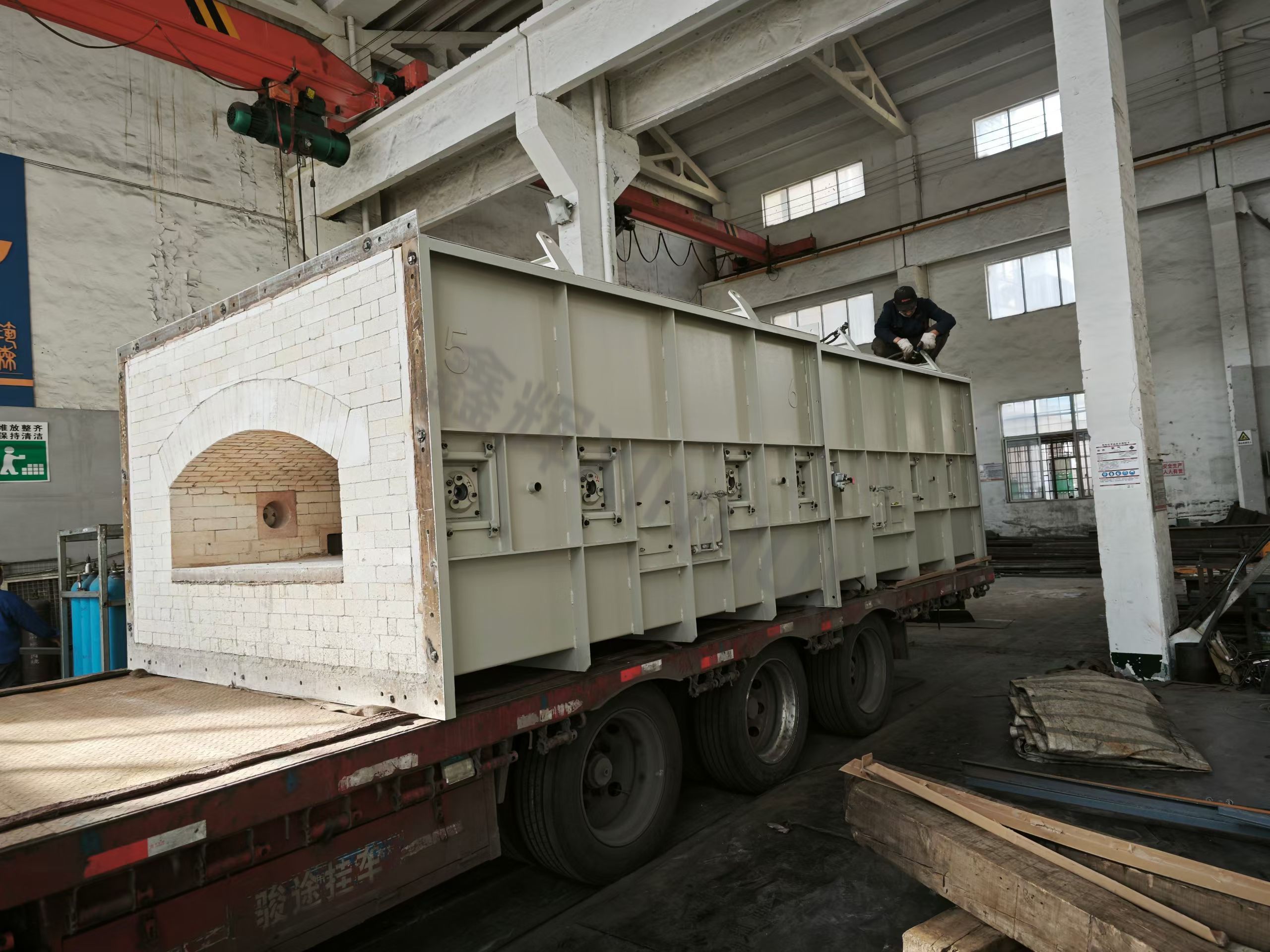
A metal products kiln line
3. Material baseline: dense fireclay vs mullite IFB (conductivity and thermal mass)
3.1 Thermal conductivity comparison: order-of-magnitude difference at the same temperature
-
Dense fireclay brick (Superduty Fireclay): at mean temperature 1800 F (about 982 deg C), K is about 10.5
Btu*in/(ft^2*h*F).- Converted to SI (
1 Btu*in/(ft^2*h*F) ~= 0.1442 W/(m*K)), k ~= 1.51W/(m*K).
- Converted to SI (
-
Mullite IFB (JM series):
- JM23: thermal conductivity at 1000 deg C about 0.19
W/(m*K); bulk density about 480kg/m^3; cold crushing strength about 1.0MPa; classification temperature about 1260deg C. - JM26: thermal conductivity at 1000 deg C about 0.33
W/(m*K); bulk density about 800kg/m^3; cold crushing strength about 1.6MPa; classification temperature about 1430deg C.
- JM23: thermal conductivity at 1000 deg C about 0.19
From conductivity alone, dense fireclay vs JM23 differs by about 1.51 / 0.19 ~= 8x. This does not include the lower thermal mass from lower density, which further improves start/stop energy for cyclic furnaces.
3.2 Heat flux magnitude: same formula, different wall heat flux
Using a one-dimensional steady conduction approximation:
Take insulation thickness L = 0.23 m and temperature difference delta T = 940 K for order-of-magnitude comparison:
- Dense fireclay (k ~= 1.51): q ~= 1.51 x 940 / 0.23 ~= 6170 W/m^2
- JM23 (k ~= 0.19): q ~= 0.19 x 940 / 0.23 ~= 776 W/m^2
Under the same thickness and temperature difference, using JM23 as the main insulation layer reduces conduction-driven heat flux by about 87%. This aligns with the engineering target of reducing surface heat flux from 631 W/m^2 to about 200 W/m^2.
4. Lining structure: separate "wear/erosion" from "insulation"
In protective-atmosphere heat-treatment furnaces, the hot-face layer must handle mechanical load, thermal shock, atmosphere fluctuations, and possible carbon/oxygen potential effects. The insulation layer's goal is to keep shell temperature and heat flux within a stable range.
A more reliable engineering approach is a multi-layer composite lining (schematic):
- Hot-face working layer: dense high-alumina/mullite-corundum bricks or castables, responsible for load and corrosion resistance.
- Transition layer: controls thermal gradient and reduces crack propagation into backup insulation.
- Backup insulation layer: JM23/JM26 mullite IFB as main insulation, significantly reducing shell heat loss.
- Cold-face sealing/steel shell system: controls air leakage and thermal bridges, determining whether "theoretical insulation" becomes real.
The logic is: let hot-face materials "carry the load," let lightweight insulation "save energy," and avoid transferring heat continuously to the shell with high-conductivity dense materials.
5. Xinhui formulation optimization system: turn R and D into a repeatable workflow
Key performance of mullite IFB (conductivity, bulk density, strength, linear change, pore stability) is influenced by both raw material variation and process curves. Trial-and-error alone cannot balance cost and consistency. Xinhui connects "formulation -> process -> testing -> application," uses data-driven surrogate models for multi-objective optimization, and uses statistical process control to lock results into a manufacturable window.
Public research confirms that machine learning can predict multiple properties for ceramics/refractories under multi-parameter conditions and identify key variables via model interpretability. In mullite-corundum ceramic multi-property prediction, gradient-boosting models achieved high fit on multiple metrics (e.g., R2 around 0.91-0.95).
5.1 System flow
6. How to account energy savings: map wall heat loss directly to specific energy
Using structured energy balance information, you can derive a calculable savings scale.
- Reference specific energy: 178 kWh/t.
- Surface loss share: about 34%.
- If surface heat flux drops from 631 to 200 W/m^2, the surface loss reduction is:
The corresponding specific energy reduction is about:
That is, considering only surface loss reduction, specific energy can drop from about 178 kWh/t to about 137 kWh/t. With additional gains from lower lining thermal mass, fewer thermal bridges/leaks, and combustion/heat recovery optimization, the total savings can grow further.
7. Material and system performance after application: visible, measurable, verifiable
In these furnaces, effectiveness shows up in three measurable signals:
- Shell surface temperature and heat flux: does the long-term trend move toward 40 deg C / 200 W/m^2.
- Specific energy per output: tracked in kWh/t with load factor, cadence, and temperature profile.
- Lining material stability: thermal conductivity (1000 deg C), bulk density, cold crushing strength, classification temperature, linear change, etc., stable within the design window.
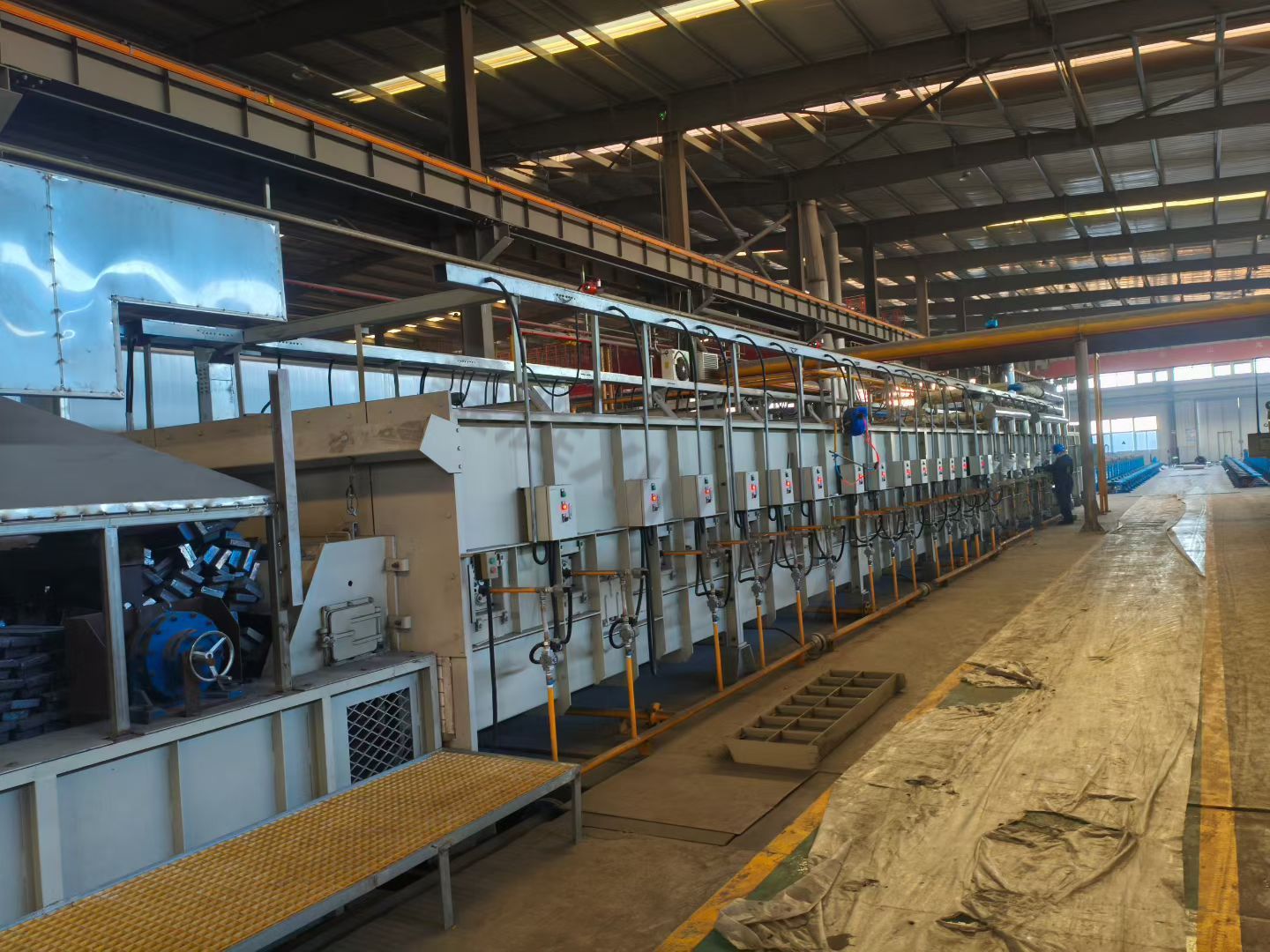
A metal products kiln line