Resistance Furnace Lightweighting
Application Scenario
Resistance furnaces/box furnaces/electric heat-treatment furnaces mostly operate in mid-to-high temperature ranges. Modular electric heating systems combined with fiber insulation structures can cover roughly 1350 deg C (depending on heating module system, fiber grade, and structural details).
These furnaces are common in multi-batch cadence, frequent start/stop, or processes requiring fast heat-up and cool-down.
What This Application Needs to Solve
- Reduce lining weight and thermal inertia.
- Push down shell temperature, reducing long-term holding losses.
- Faster heat-up/cool-down, shorter recovery time.
- Control heat leakage at doors and interfaces to reduce "fixed hot spots."
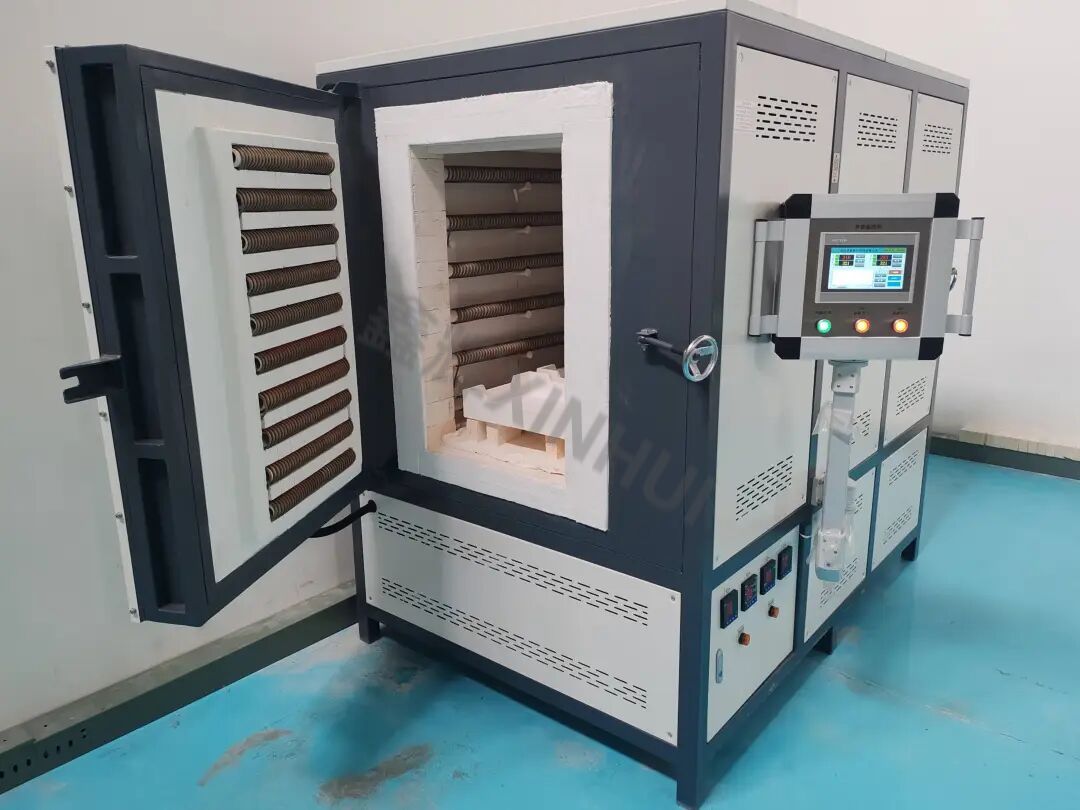
Xinhui Implementation in Electric Furnaces
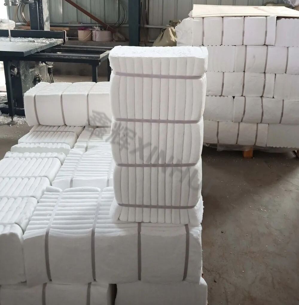
Fiber backup insulation (primary lightweighting)
Ceramic fiber modules/blankets/boards serve as the main insulation layer, forming a continuous thermal resistance layer that directly reduces wall heat storage and shell heat loss. Fiber module temperature grades can cover 1000-1430 deg C; select grade and hot-face protection thickness by service temperature.
Door sealing (key to leakage and hot-spot control)
Use fiber rope, fiber paper/gaskets, and compression sealing structures to address door gap leakage and door-frame hot spots. Door seals are better managed as serviceable parts at doors, openings, and expansion joints.
IFB as supplemental structural parts (stability and durability)
Where stronger structural stability is needed (local load bearing, thermal bridge breaks, around access ports, or certain backup areas), use lightweight IFB as backup insulation or local thermal breaks. IFB provides "stable geometry + controlled thermal gradient" and is commonly used as a backup layer behind the main lining.
Modular heating and fiber structures (shorter maintenance cycles)
Modular heating units (heating elements integrated with fiber forms) allow fast replacement and standardized structures, suitable for batch equipment and maintenance cadence. Such structures can be rated up to around 1350 deg C.
On-site Data-Driven Optimization Entry Points
Track three curves: shell temperature, power curve, and soak-stage energy. Turn them into a "calculable" heat-loss map.
Approximate heat loss during soak
Use a simplified relation to link soak-stage power and shell heat loss (for comparison and iteration, not lab-grade accuracy):
- Approximation: P_hold ~= U * A * (T_in - T_amb) + P_leak
- U is determined by lining material combinations and thickness; P_leak comes mainly from doors, interfaces, and view ports.
Iteration actions
- Thermal imaging or spot shell temperature to locate hot zones.
- Prioritize hot zones: door sealing, interface thermal breaks, continuous overlaps.
- Then non-hot zones: optimize lining thickness and material grades (manufacturability and maintainability as constraints).
- Target signals: lower soak-stage power baseline, converging shell hot spots, shorter recovery time.
Some fiber box furnace product pages also state "lower surface temperature" as a structural goal, e.g., dual-layer cooling to keep shell temperature near ambient during high-temperature operation, with a max around 50 deg C.
Changes After Implementation
- Shell hot spots converge; door frame and opening temperature rise decreases.
- Smoother soak-stage power, lower long-term heat loss.
- Faster heat-up/cool-down response; smoother start/stop and multi-batch cadence.
- Maintenance focused on "seals/modules/local parts," with shorter repair paths.