Semiconductor Atmosphere Furnace Lining Upgrade
Lower shell temperature, stabilize temperature field, reduce energy use
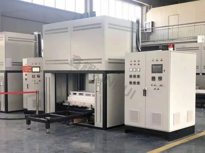
Application Scenario
Customers use high-temperature atmosphere furnaces for semiconductor manufacturing, for annealing/diffusion/oxidation and other heat-treatment steps. The furnaces run long-term in mid-to-high temperature ranges, with process gases mainly nitrogen, inert gas, and forming gas (H2-N2 mixture), covering up to around 1100 deg C.
The core needs are clear: stable temperature distribution, low operational fluctuation, clean and fast maintenance, and controlled shell temperature rise to avoid hot spots and energy use being "fixed" by structural defects.
Typical Issues Before Upgrade
- Local shell hot spots at door frames, view ports, and gas interfaces/flanges; repeat at the same locations, i.e., thermal bridges.
- Larger chamber temperature gradients; control system compensation increases; overshoot and recovery time lengthen.
- Frequent start/stop and batch switching; lining heat capacity too high, slow ramp-up, high standby loss.
- High requirement for hot-face stability; any dusting/chipping/falling debris raises maintenance cost and risk.
Xinhui Implementation
The plan focuses on three things: reliable hot face, insulated backup, and zero thermal bridges.
Hot-face working layer (load and atmosphere scouring)
Use a dense refractory system (brick/castable) for the hot-face layer, prioritizing mechanical strength, scouring resistance, and thermal shock. The structure should remain "no spalling, no loosening" long-term.
Backup insulation layer (shell temperature control and heat-loss reduction)
Lightweight mullite IFB as the main insulation to reduce shell heat loss and heat storage, making start/stop more responsive. Material selection follows graded matching by temperature window: with sufficient temperature margin, prioritize lower conductivity and lower heat storage to avoid raising both conductivity and heat capacity.
Ceramic fiber insulation and sealing (complex areas and continuity)
Use fiber blankets/boards/modules with sealing ropes/paper around doors, access ports, view ports, and interfaces to provide continuous insulation and multi-layer sealing, addressing complex geometry, thermal expansion, and frequent disassembly.
Thermal bridge cleanup (door frame/view port/interface flange)
Treat door frames, view ports, and interface flanges as dedicated items: thermal breaks, insulation pads, compression sealing, and continuous overlaps. If thermal bridges remain, thicker insulation will still be short-circuited locally.
On-site Iteration
- Locate with three data sets: temperature curves (set vs actual), power curves (ramp/soak/standby), shell temperature points (door frame/interface/corners/shell mid, thermal imaging or spot measurement).
- Find root cause by overlaying "hot spot locations x zones with strongest compensation": bridges, gaps, discontinuous overlaps, penetrations.
- Fixed sequence: address thermal bridges and sealing continuity first, then fine-tune backup layering/thickness, then standardize construction details and bake-out curve.
Changes After Commissioning
- Hot spots shrink: door frame, interfaces, access ports show smaller local high-temp zones and more uniform shell temperature rise.
- Smoother power curve: reduced compensation fluctuation in soak; less zone-to-zone "tug-of-war."
- Faster ramp and recovery: less heat capacity "fill-in" during start/stop; batch switching smoother.
- Longer maintenance intervals: hot-face structure more stable, sealing more reliable, less frequent cleaning and patching.